PLL Chart for this exciter
-
- who u callin ne guy bruv
- Posts: 11
- Joined: Mon Dec 15, 2014 4:27 pm
PLL Chart for this exciter
Hi,
I am wondering if someone could help me with finding the pll look up table for this exciter?
I did get help on the old radionecks forum but unfortunately I didn't save the information
Many thanks
I am wondering if someone could help me with finding the pll look up table for this exciter?
I did get help on the old radionecks forum but unfortunately I didn't save the information
Many thanks
-
- tower block dreamin
- Posts: 272
- Joined: Wed Oct 15, 2014 9:25 pm
Re: PLL Chart for this exciter
Was it not something like
all switch of 87,50
and then
0,1-0,2-0,4-0,8-1,6-3,2-6,4-12,8
for switch
1 2 3 4 5 6 7 8
so if you want the pll on 94.2
94,2 - 87,5 =6,7 so switch 7 and 1 and 2 must be on
all switch of 87,50
and then
0,1-0,2-0,4-0,8-1,6-3,2-6,4-12,8
for switch
1 2 3 4 5 6 7 8
so if you want the pll on 94.2
94,2 - 87,5 =6,7 so switch 7 and 1 and 2 must be on
- teckniqs
- proppa neck!
- Posts: 3180
- Joined: Thu Aug 21, 2014 11:37 am
Re: PLL Chart for this exciter
That is a D*** B**man PLL, I'm sure if you can tell us what it's currently set to we could easily work out how it's done looking at the switch positions for its current frequency??
-
- who u callin ne guy bruv
- Posts: 11
- Joined: Mon Dec 15, 2014 4:27 pm
Re: PLL Chart for this exciter
Hi there,
It is currently set to 106.5
off,on,on,on,on,on,off,on
Cheers lads!
It is currently set to 106.5
off,on,on,on,on,on,off,on
Cheers lads!
-
- who u callin ne guy bruv
- Posts: 11
- Joined: Mon Dec 15, 2014 4:27 pm
Re: PLL Chart for this exciter
RF-Head, your method seems to add up for the frequency it's set to. I'll try retune it when I get my hands on it.
- teckniqs
- proppa neck!
- Posts: 3180
- Joined: Thu Aug 21, 2014 11:37 am
Re: PLL Chart for this exciter
He's called RF Head for a very good reason.
Re: PLL Chart for this exciter
Is there any other components on the underside of this board? Looks very minimalistic, what chip(s) it use?
-
- no manz can test innit
- Posts: 127
- Joined: Sat Aug 30, 2014 11:21 pm
Re: PLL Chart for this exciter
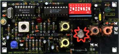
I asked the same question on the original Radionecks forum. Apparently there is some surface mount stuff on the other side - I presume the PLL chip, and the VCO.s2000 wrote:Is there any other components on the underside of this board? Looks very minimalistic, what chip(s) it use?
- teckniqs
- proppa neck!
- Posts: 3180
- Joined: Thu Aug 21, 2014 11:37 am
Re: PLL Chart for this exciter
IIRC you are correct, there is a small SM chip on the underside.
-
- no manz can test innit
- Posts: 227
- Joined: Tue Dec 02, 2014 11:03 am
Re: PLL Chart for this exciter
I would think a chip, and probably a few transistors (about 3 at a guess)......
Quite possibly a varicap or two. I can't see any in the piccy.
-
- tower block dreamin
- Posts: 272
- Joined: Wed Oct 15, 2014 9:25 pm
Re: PLL Chart for this exciter
1x mc145170
3x bfr93 or SMT version of a mpsh10
2x varicap
Thats all
3x bfr93 or SMT version of a mpsh10
2x varicap
Thats all
-
- no manz can test innit
- Posts: 227
- Joined: Tue Dec 02, 2014 11:03 am
Re: PLL Chart for this exciter
Looks like the RF circuitry, is either the same, or very similar, to his old (pre SM) driver boards; replacing what used to be BSX20 / 2N2369, with BFR93 on the track side.RF-Head wrote:1x mc145170
3x bfr93 or SMT version of a mpsh10
2x varicap
Thats all
-
- ne guy
- Posts: 5
- Joined: Sun Dec 28, 2014 5:34 pm
Re: PLL Chart for this exciter
Does anyone have a circuit diagram / PCB layout for this design? Even a detailed closeup of each side of the board with be useful. Cheers
-
- ne guy
- Posts: 5
- Joined: Sun Dec 28, 2014 5:34 pm
Re: PLL Chart for this exciter
Thanks pjeva.
Were you referring to this BW unit....
.... 'cos they look quite different?
Were you referring to this BW unit....
.... 'cos they look quite different?
-
- no manz can test innit
- Posts: 127
- Joined: Sat Aug 30, 2014 11:21 pm
Re: PLL Chart for this exciter
From what I've seen, I think all the “London Rigs” are based around the same circuit with maybe a few difference between them. Take a look at the thread Analyser's Draw Of Pirate History, and you'll see they all pretty much use the same components and layout, with differences in the PLL or single/double sided. If you have the schematic Rig Doctor put out on the original Radionecks you should be able to understand the rest. If you don't have it I can repost it?!
-
- no manz can test innit
- Posts: 123
- Joined: Thu Sep 04, 2014 11:20 am
Re: PLL Chart for this exciter
rigdoctors schematic
You do not have the required permissions to view the files attached to this post.