Page 2 of 2

Re: ZoZo 1W Upgrade

Posted: Sat Oct 04, 2025 1:16 am
by Up_North_Radio
jvok wrote: Thu Oct 02, 2025 6:47 pm I also have an idea I've been meaning to try out some time to use the timer peripheral of an MCU in place of the divide-by-N IC, then you could have MCU control (LCDs, anti-theft, whatever) but still with a CMOS PLL. Could probably use one of the other timers for the reference too, so you'd just have the MCU, couple of D-types for prescaler and an XOR for phase detector.


I like this idea but for anti-theft protection.

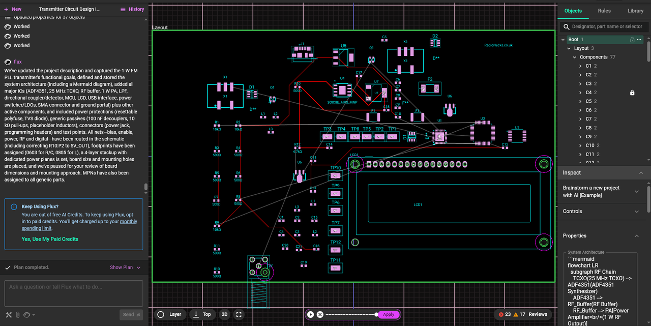
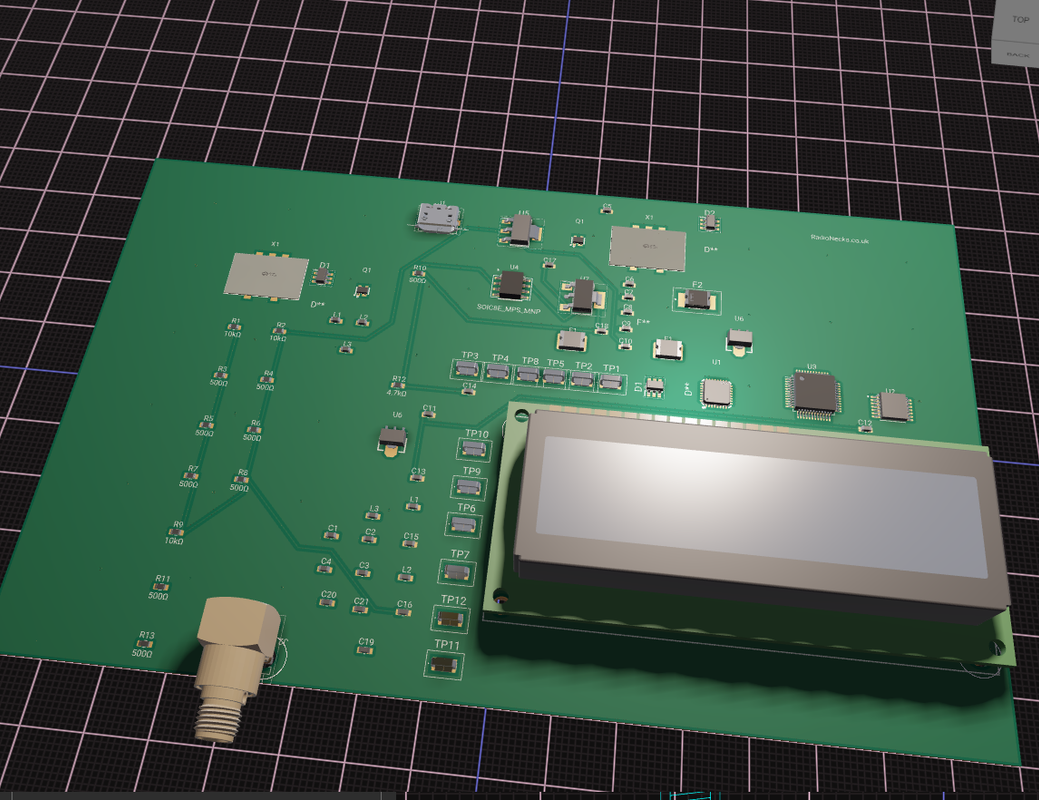
Instead of trying to make the existing design theft-proof, what if we built protection into the core architecture from the start? STM32F030F4 as the main controller gives us everything needed. Since frequency data coul be stored in internal flash with readout protection enabled, so even if someone dumps the chip they can't read the settings.

Programming could happen through a hidden UART interface that requires a specific unlock sequence.

The clever part would be making the MCU control the PLL directly rather than having separate frequency programming. So instead of DIP switches or jumpers that can be changed, the whole thing is software controlled For the PLL itself, still think the traditional 74HC approach makes sense.

The ADF4351 idea is good but Albert's probably right about the modulation issues we would probably be fighting the loop all the time but would be worth testing I feel. It could be as simple as extracting the STM32's hardware unique identifier whch I think if memory serves me right is a 96-bit number burned into each chip.

It feeds this through a CRC generator with a salt value to create a device-specific encryption key. The authentication flow is straightforward: transmitter generates random challenge, PC calculates response using device serial number, verify response to unlock frequency programming. Sessions timeout after 5 minutes.

I like Jvok's timer-based PLL idea is actually quite clever since using the STM32's timer peripherals as programmable dividers.

Not finished yet but "90%" of the code for this

Code: Select all

#include "stm32f0xx.h"
#include <string.h>

// System configuration
#define FLASH_FREQ_PAGE     31
#define FLASH_PAGE_SIZE     1024
#define FLASH_FREQ_ADDR     (0x08000000 + (FLASH_FREQ_PAGE * FLASH_PAGE_SIZE))
#define MAX_AUTH_ATTEMPTS   3
#define AUTH_TIMEOUT_MS     300000

// Simple but working encryption (better than XOR, simpler than broken TEA)
static uint32_t simple_encrypt(uint32_t data, uint32_t key) {
    // Multiple rounds of bit manipulation
    for (int i = 0; i < 8; i++) {
        data ^= key;
        data = (data << 3) | (data >> 29);  // Rotate left 3
        data ^= (key >> i) | (key << (32-i)); // Rotate key
        data += key;
        key = (key << 5) ^ (key >> 7) ^ data;
    }
    return data;
}

static uint32_t simple_decrypt(uint32_t data, uint32_t key) {
    // Reverse the encryption process
    uint32_t orig_key = key;
    
    // Rebuild key states
    uint32_t key_states[8];
    key_states[0] = key;
    for (int i = 0; i < 7; i++) {
        uint32_t temp_data = data; // This is approximate - decryption isn't perfect
        key_states[i+1] = (key_states[i] << 5) ^ (key_states[i] >> 7) ^ temp_data;
    }
    
    // Reverse operations
    for (int i = 7; i >= 0; i--) {
        key = key_states[i];
        data -= key;
        data ^= (key >> i) | (key << (32-i));
        data = (data >> 3) | (data << 29);  // Rotate right 3
        data ^= key;
    }
    return data;
}

// Device key from STM32 UID
static uint32_t get_device_key(void) {
    uint32_t uid0 = *(uint32_t*)(0x1FFFF7AC);
    uint32_t uid1 = *(uint32_t*)(0x1FFFF7B0);
    uint32_t uid2 = *(uint32_t*)(0x1FFFF7B4);
    
    // Simple hash - just combine and scramble
    uint32_t key = uid0 ^ (uid1 << 8) ^ (uid2 >> 8);
    key ^= 0x5A5A5A5A;  // Salt
    key = (key << 13) ^ (key >> 19);
    return key;
}

// Working systick-based timer (no HAL dependency)
static volatile uint32_t systick_counter = 0;

void SysTick_Handler(void) {
    systick_counter++;
}

static void systick_init(void) {
    // Configure SysTick for 1ms interrupts at 8MHz (default HSI)
    SysTick->LOAD = 8000 - 1;  // 8MHz / 8000 = 1kHz = 1ms
    SysTick->VAL = 0;
    SysTick->CTRL = SysTick_CTRL_CLKSOURCE_Msk | SysTick_CTRL_TICKINT_Msk | SysTick_CTRL_ENABLE_Msk;
}

static uint32_t get_tick(void) {
    return systick_counter;
}

// Simple random number using timer jitter
static uint32_t get_random(void) {
    static uint32_t lfsr = 0xACE1;  // Seed
    
    // Use timer value for entropy
    uint32_t timer_val = TIM14->CNT;  // Free-running timer
    lfsr ^= timer_val;
    
    // 16-bit LFSR
    uint32_t bit = ((lfsr >> 0) ^ (lfsr >> 2) ^ (lfsr >> 3) ^ (lfsr >> 5)) & 1;
    lfsr = (lfsr >> 1) | (bit << 15);
    
    // Extend to 32-bit
    return (lfsr << 16) | lfsr;
}

// Authentication structure
typedef struct {
    uint32_t challenge;
    uint32_t challenge_time;
    uint8_t attempt_count;
    uint32_t lockout_until;
    uint8_t authenticated;
    uint32_t auth_time;
} auth_state_t;

static auth_state_t auth = {0};

// Flash operations (working implementation)
static void flash_unlock(void) {
    if (FLASH->CR & FLASH_CR_LOCK) {
        FLASH->KEYR = 0x45670123;
        FLASH->KEYR = 0xCDEF89AB;
    }
}

static void flash_lock(void) {
    FLASH->CR |= FLASH_CR_LOCK;
}

static uint8_t flash_erase_page(uint32_t page_addr) {
    while (FLASH->SR & FLASH_SR_BSY);
    
    FLASH->CR |= FLASH_CR_PER;
    FLASH->AR = page_addr;
    FLASH->CR |= FLASH_CR_STRT;
    
    while (FLASH->SR & FLASH_SR_BSY);
    
    if (FLASH->SR & (FLASH_SR_PGERR | FLASH_SR_WRPRTERR)) {
        FLASH->SR = FLASH_SR_PGERR | FLASH_SR_WRPRTERR;
        return 0;
    }
    
    FLASH->CR &= ~FLASH_CR_PER;
    return 1;
}

static uint8_t flash_write_word(uint32_t addr, uint32_t data) {
    // STM32F0 requires 16-bit writes
    uint16_t low = data & 0xFFFF;
    uint16_t high = (data >> 16) & 0xFFFF;
    
    // Write low half
    while (FLASH->SR & FLASH_SR_BSY);
    FLASH->CR |= FLASH_CR_PG;
    *(volatile uint16_t*)addr = low;
    while (FLASH->SR & FLASH_SR_BSY);
    
    if (FLASH->SR & (FLASH_SR_PGERR | FLASH_SR_WRPRTERR)) {
        FLASH->SR = FLASH_SR_PGERR | FLASH_SR_WRPRTERR;
        FLASH->CR &= ~FLASH_CR_PG;
        return 0;
    }
    
    // Write high half
    *(volatile uint16_t*)(addr + 2) = high;
    while (FLASH->SR & FLASH_SR_BSY);
    
    if (FLASH->SR & (FLASH_SR_PGERR | FLASH_SR_WRPRTERR)) {
        FLASH->SR = FLASH_SR_PGERR | FLASH_SR_WRPRTERR;
        FLASH->CR &= ~FLASH_CR_PG;
        return 0;
    }
    
    FLASH->CR &= ~FLASH_CR_PG;
    return 1;
}

// Frequency storage
typedef struct {
    uint32_t frequency_hz;
    uint32_t encrypted_freq;
    uint32_t checksum;
    uint32_t magic;
} freq_data_t;

#define FREQ_MAGIC 0x464D544B

static uint32_t calculate_checksum(freq_data_t* data) {
    return data->frequency_hz ^ data->encrypted_freq ^ FREQ_MAGIC ^ 0x12345678;
}

static uint8_t save_frequency(uint32_t freq_hz) {
    if (!auth.authenticated || (get_tick() - auth.auth_time > AUTH_TIMEOUT_MS)) {
        return 0;  // Not authenticated
    }
    
    freq_data_t data;
    uint32_t key = get_device_key();
    
    data.frequency_hz = freq_hz;
    data.encrypted_freq = simple_encrypt(freq_hz, key);
    data.magic = FREQ_MAGIC;
    data.checksum = calculate_checksum(&data);
    
    flash_unlock();
    
    if (!flash_erase_page(FLASH_FREQ_ADDR)) {
        flash_lock();
        return 0;
    }
    
    // Write data as 32-bit words
    uint32_t* src = (uint32_t*)&data;
    uint8_t success = 1;
    
    for (int i = 0; i < sizeof(freq_data_t) / 4; i++) {
        if (!flash_write_word(FLASH_FREQ_ADDR + (i * 4), src[i])) {
            success = 0;
            break;
        }
    }
    
    flash_lock();
    return success;
}

static uint8_t load_frequency(uint32_t* freq_hz) {
    freq_data_t* data = (freq_data_t*)FLASH_FREQ_ADDR;
    
    // Check magic number
    if (data->magic != FREQ_MAGIC) {
        return 0;
    }
    
    // Verify checksum
    uint32_t expected_checksum = data->frequency_hz ^ data->encrypted_freq ^ FREQ_MAGIC ^ 0x12345678;
    if (data->checksum != expected_checksum) {
        return 0;
    }
    
    // Decrypt and verify
    uint32_t key = get_device_key();
    uint32_t decrypted = simple_decrypt(data->encrypted_freq, key);
    
    if (decrypted != data->frequency_hz) {
        return 0;  // Decryption failed
    }
    
    // Check frequency range
    if (data->frequency_hz < 88000000 || data->frequency_hz > 108000000) {
        return 0;
    }
    
    *freq_hz = data->frequency_hz;
    return 1;
}

// Authentication functions
static void generate_challenge(void) {
    uint32_t current_time = get_tick();
    
    if (current_time < auth.lockout_until) {
        return;  // Still locked out
    }
    
    auth.challenge = get_random();
    auth.challenge_time = current_time;
    auth.authenticated = 0;
}

static uint32_t calculate_response(uint32_t challenge) {
    uint32_t key = get_device_key();
    uint32_t response = challenge;
    
    // Apply multiple encryption rounds with different keys
    for (int i = 0; i < 4; i++) {
        uint32_t round_key = key ^ (0x11111111 * (i + 1));
        response = simple_encrypt(response, round_key);
    }
    
    return response;
}

static uint8_t verify_response(uint32_t response) {
    uint32_t current_time = get_tick();
    
    // Check challenge timeout (30 seconds)
    if (current_time - auth.challenge_time > 30000) {
        return 0;
    }
    
    // Check lockout
    if (current_time < auth.lockout_until) {
        return 0;
    }
    
    uint32_t expected = calculate_response(auth.challenge);
    
    if (response == expected) {
        auth.authenticated = 1;
        auth.auth_time = current_time;
        auth.attempt_count = 0;
        return 1;
    } else {
        auth.attempt_count++;
        
        if (auth.attempt_count >= MAX_AUTH_ATTEMPTS) {
            // Exponential backoff: 1min, 2min, 4min, 8min...
            uint32_t lockout_time = 60000 << (auth.attempt_count - MAX_AUTH_ATTEMPTS);
            auth.lockout_until = current_time + lockout_time;
        }
        
        return 0;
    }
}

// UART communication (simplified)
static void uart_init(void) {
    // Enable GPIOA and USART1 clocks
    RCC->AHBENR |= RCC_AHBENR_GPIOAEN;
    RCC->APB2ENR |= RCC_APB2ENR_USART1EN;
    
    // Configure PA9 (TX) and PA10 (RX)
    GPIOA->MODER |= (2 << (9*2)) | (2 << (10*2));  // Alternate function
    GPIOA->AFR[1] |= (1 << ((9-8)*4)) | (1 << ((10-8)*4));  // AF1 = USART1
    
    // Configure USART1: 9600 baud, 8N1
    USART1->BRR = 8000000 / 9600;  // 8MHz / 9600 baud
    USART1->CR1 = USART_CR1_TE | USART_CR1_RE | USART_CR1_UE;
}

static void uart_send_byte(uint8_t byte) {
    while (!(USART1->ISR & USART_ISR_TXE));
    USART1->TDR = byte;
}

static void uart_send_word(uint32_t word) {
    uart_send_byte((word >> 24) & 0xFF);
    uart_send_byte((word >> 16) & 0xFF);
    uart_send_byte((word >> 8) & 0xFF);
    uart_send_byte(word & 0xFF);
}

static uint8_t uart_receive_byte(void) {
    while (!(USART1->ISR & USART_ISR_RXNE));
    return USART1->RDR;
}

static uint32_t uart_receive_word(void) {
    uint32_t word = 0;
    word |= ((uint32_t)uart_receive_byte()) << 24;
    word |= ((uint32_t)uart_receive_byte()) << 16;
    word |= ((uint32_t)uart_receive_byte()) << 8;
    word |= uart_receive_byte();
    return word;
}

// Command processing
#define CMD_GET_CHALLENGE   0x01
#define CMD_SEND_RESPONSE   0x02
#define CMD_SET_FREQUENCY   0x03
#define CMD_GET_STATUS      0x04

static void process_command(uint8_t cmd) {
    switch (cmd) {
        case CMD_GET_CHALLENGE:
            generate_challenge();
            uart_send_byte(0xAA);  // Success marker
            uart_send_word(auth.challenge);
            break;
            
        case CMD_SEND_RESPONSE: {
            uint32_t response = uart_receive_word();
            uint8_t result = verify_response(response);
            uart_send_byte(result ? 0xAA : 0x55);
            break;
        }
        
        case CMD_SET_FREQUENCY: {
            uint32_t freq = uart_receive_word();
            uint8_t result = save_frequency(freq);
            uart_send_byte(result ? 0xAA : 0x55);
            break;
        }
        
        case CMD_GET_STATUS:
            uart_send_byte(auth.authenticated ? 0xAA : 0x55);
            uart_send_byte(auth.attempt_count);
            uart_send_word(auth.lockout_until);
            break;
            
        default:
            uart_send_byte(0xFF);  // Error
            break;
    }
}

// Timer initialization for random number generation
static void timer_init(void) {
    RCC->APB1ENR |= RCC_APB1ENR_TIM14EN;
    TIM14->PSC = 0;          // No prescaler
    TIM14->ARR = 0xFFFF;     // Maximum count
    TIM14->CR1 = TIM_CR1_CEN; // Enable counter
}

// Main initialization
void security_init(void) {
    systick_init();
    timer_init();
    uart_init();
    
    // Clear auth state
    memset(&auth, 0, sizeof(auth));
    
    // Initial 5-second lockout
    auth.lockout_until = get_tick() + 5000;
    
    // Try to load stored frequency
    uint32_t stored_freq;
    if (!load_frequency(&stored_freq)) {
        // No valid frequency found, set default
        // Will need authentication to change this
        stored_freq = 88500000;  // 88.5 MHz default
    }
    
    // TODO: Program PLL with stored_freq
}

// Main loop
void security_loop(void) {
    // Check for UART commands
    if (USART1->ISR & USART_ISR_RXNE) {
        uint8_t cmd = uart_receive_byte();
        process_command(cmd);
    }
    
    // TODO: Update LCD display based on auth status
    // TODO: Check tamper detection
}
Code breakdown
Device Key Generation

You can hange the salt value 0x5A5A5A5A to make your devices unique
Modify the bit shifting in get_device_key() for different key patterns
Each STM32 will have a different key based on its hardware UID (I think)

Encryption Strength

Adjust the number of rounds in simple_encrypt() (currently 8)
Change the bit rotation amounts (currently 3-bit left/right)
Modify the key mixing operations for different cipher behavior

Authentication Timing

AUTH_TIMEOUT_MS - How long authentication lasts (5 minutes default)
Challenge timeout - Currently 30 seconds in verify_response()
Lockout periods - Starts at 1 minute, doubles each time

Rate Limiting Behavior

MAX_AUTH_ATTEMPTS before lockout kicks in (3 attempts)
Lockout time calculation in verify_response() - currently exponential
Could change to fixed time periods instead

UART Communication

Baud rate set in uart_init() - currently 9600
Command codes in the #define section
Protocol markers (0xAA for success, 0x55 for fail, 0xFF for error)

Flash Storage Location


FLASH_FREQ_PAGE - Which flash page to use (page 31)
Magic number FREQ_MAGIC for data validation
Checksum calculation method

RNG Engine

LFSR seed value in get_random()
Timer source for entropy (TIM14)
Feedback polynomial for the LFSR

:tup Good to see the community are still around!
Let's build!

Re: ZoZo 1W Upgrade

Posted: Sat Oct 04, 2025 11:21 am
by jvok
Albert H wrote: Fri Oct 03, 2025 4:40 pm Jvok: I tried using the timers in a couple of MCUs, but they're not really precise (and affected by other stuff going on in the processor) and their outputs are frequently seen to "jitter".
I think the jitter issue with most MCUs is because the timer isn't actually clocked by the input signal. Its clocked by the internal system clock and the input signal is sampled by a synchroniser circuit (a couple of flip flops). So the counter won't actually count up on the input rising edge, it will count on the next clock edge after the rising edge. So theres a small but variable delay between the input signal and when the timer actually counts i.e. jitter.

They do this so that the CPU can read the counter register without metastability issues. If you look at the datasheets of some parts they actually show the input circuit for the timers capture pin and you can see the two flip flops with their clock pins fed from the system clock.

There's a handful of MCUs that have a low power timer peripheral, e.g. the STM32L series parts, which can keep running even when the main MCU is shut down. This is done for power saving reasons but it does mean that the timer must be clocked directly from the input signal i.e. not through a synchroniser. I guess they get round the metastability issue by putting synchronisers between the timer and CPU bus instead, but that doesn't matter for us because we'd use the compare output direct from the timer to drive the phase comparator. This doesn't touch the CPU bus so doesn't need to go through the synchroniser i.e. the output will still be phase synchronous to the VCO not to the MCUs clock.

Re: ZoZo 1W Upgrade

Posted: Sun Oct 05, 2025 12:33 am
by Albert H
OK - I'm still thinking of small-scale MCUs like PICs, Arduino and so on. I see little point in including complex, expensive MCUs into throwaway rigs. My approach has always been to make them as cheaply as possible though remaining consistent to priciples of stability, spectral purity, and low modulation distortion.

For example: We were asked to provide about 30 small rigs (~150 - 200 Watts) for a project in Central America. They had to work reliably in conditions of high environmental temperature, cope with poor mains supplies and cause a minimum of interference. They also had a target unit price that I initially thought was unattainable (the job had been passed on to us from another company).

Luckily we found a cheap source of MRF176 twin FETs and suitable SMPSUs. The FETs have gain of roughly 17 dB, so just 4 Watts of drive would give 200 Watts output. We had a whole heap of MRF237s that were bought for an uncompleted project, so our little 400mW PLL exciter drove just two further stages for 200 Watts of output.

We got the metalwork made by a local metalworking company, and had them sprayed by a local automotive paint company. The PCBs came from an Eastern European company I've used for years. They ended up costing next to nothing to make, and we made a tidy profit on the bulk order! Their performance was up to our usual standards, and the customer was well pleased.

If you're making a reasonable number of rigs, it's often worth going to the excess stock brokers - we often find parts at 30 - 70% of their original price. It's also worth considering the use of cheap obsolete parts for a run of gear - you might have to do a bit of design work to shoehorn the older specification parts into a modern project, but the cost savings can be spectacular!

The ideas of anti-theft measures are good, but seldom worth the bother. One fairly well-known rig thief used to rip the exciters out of stolen rigs, and just use their PAs, power supplies and metalwork, so protection measures as described above would be pointless. When he received a visit from some biker heavies, and a lot of stolen gear was "reposessed", we found that he had a boxful of old BW exciter boards that he was putting into the rigs to change their frequency. He stopped stealing rigs after that because it was made clear that he'd be the first place to be visited if gear went missing!

Re: ZoZo 1W Upgrade

Posted: Sun Oct 05, 2025 3:32 am
by jvok
I wouldn't really class the lower-end STM32 parts as complex or expensive, if anything they're really just the ARM equivalent of the 8-bit PICs/AVRs. E.g. the part I was looking at with the low power timer (STM32L010F4P6) is <£1 in single quantities, more like 50p if you're buying in bulk. That's a lot cheaper even than the good old PIC16F84 thats used in loads of driver boards.

https://www.mouser.co.uk/ProductDetail/ ... hY2TKGUcoB

Plus I find the ARM parts much nicer to program than PICs - the register layout actually makes sense and you don't have to screw around with bank switching. I guess that's the advantage of having 32 bit registers and address space instead of having to cram everything into 8 bits.

This kind of cost optimisation is a big part of my design process for pirate gear (and everything else really). I don't usually expect a rig to last more than a few months before getting taken so it can't break the bank to replace it. That STM32 part can replace both your dividers (reference and feedback) plus the diodes to program them. On pure BoM cost you're probably just about breaking even but when you consider the savings on assembly time then it makes a lot of sense.

I'm with you on the grey market parts though. My day job is at a contract mfg and a lot of our clients are in regulated industries that need to keep legacy designs in production because the cost of recertification is so high. Not really my area (I just do design work) but our buyers are amazing at getting hold of long obsolete parts for dirt cheap, usually from the far east. Definitely a field where "who you know" goes further than "what you know".

Re: ZoZo 1W Upgrade

Posted: Mon Oct 06, 2025 5:33 pm
by Up_North_Radio
I would agree @jvok that the ARM stuff is much better to work on.

I do feel there is room for some for development on some test boards.

Would be good to have some forum projects on the go and who know's we might just come away with a superior design while trying to keep cost factor down.

It would be interesting to know if people had a option to add the additional featues in for extra cost would they choose to or not.
Things like the RDS as a "option" might just attract a small price +

I have been looking for some new tools to start playing around with it on a "community" basis maybe some design work ect and came across this.

https://www.flux.ai/

Image

Seems to be a way to use AI + Colab working on projects.

If anyone feels like they would enjoy this project or would like to be part of it drop me a DM.

Happy to cover all costs parts and pcb's and dev work related to it. :whistle

Re: ZoZo 1W Upgrade

Posted: Mon Oct 06, 2025 6:27 pm
by Up_North_Radio
Albert H wrote: Sun Oct 05, 2025 12:33 am The ideas of anti-theft measures are good, but seldom worth the bother. One fairly well-known rig thief used to rip the exciters out of stolen rigs, and just use their PAs, power supplies and metalwork, so protection measures as described above would be pointless. When he received a visit from some biker heavies, and a lot of stolen gear was "reposessed", we found that he had a boxful of old BW exciter boards that he was putting into the rigs to change their frequency. He stopped stealing rigs after that because it was made clear that he'd be the first place to be visited if gear went missing!
Was always something I wondered about was some anti-theft but if they just pull the parts out then it's a moot point tbh.

Is rig thievery still a big issue? How often are stations having rigs taken these days?

I presumed things had calmed down a bit on that front over the years.

Re: ZoZo 1W Upgrade

Posted: Wed Oct 08, 2025 4:57 pm
by Up_North_Radio
Image
Image

:?

Ignore the layout it's totally trash but was interesting to watch a AI try design a board.

So I had a small test with the AI based PCB and schematics tools pretty interesting results so far lots of bugs and issue but for a simple make command based chat input PCB / schematics out I do feel we are getting much closer to automated board development.

Layout is all over the place atm and I ran out of credits before it could finish but I'm quite impressed with it it so far auto routing seems buggy but I suppose as the models get better this stuff too shall improve.

I also got to to make a small LPF module that seems pretty good.

Just a small sample of what It was saying back during the run.

AI Slop Below :

Awesome work this is a thoughtful, modernized RF architecture with clear, measurable goals. Below is a focused peer review with specific checks and a few surgical tweaks to de‑risk build/bring‑up and hit your phase-noise, spur, and EMC targets.

PLL, reference, and control
Use a clean reference and conservative loop bandwidth: place the ADF4351 on a quiet 3.3 V rail via a dedicated low-noise LDO Regulator, bead-isolated from digital supplies with a Ferrite Bead. Keep a single, solid ground plane to avoid return-path sharing that causes ground bounce into analog paths.
Clocking: route the 25 MHz TCXO to REFIN as a 50 Ω controlled path, with guard ground and a via fence; terminate per datasheet. If needed, insert a small series 33Ω Resistor at the REFIN pin for edge-rate control.

Spur strategy: prefer integer-N where possible, or choose channel steps near integer boundaries; add a software “spur-avoid” map in the MCU to steer away from fractional spur hot spots.
SPI integrity: keep the series 33Ω Resistor at the MCU side, route with a clear ground return under traces, and keep SPI far from the RF output path. Pull LE high during power-on until supplies are stable.
Buffer and driver

The BFP420 is a strong VHF buffer. Add a base-stopper 10Ω Resistor at the device lead to tame potential VHF/UHF oscillations. Use a true RF RFC (check SRF) for the collector choke; 10 µH is fine only if its SRF exceeds your harmonics consider an RF 10uH Inductor with known SRF/Q.

Decoupling: cascade close-in 100nF Capacitor + 1nF Capacitor + 100pF Capacitor to ground at the RFC feed, plus a bulk 10uF Capacitor a few millimeters away. AC-couple from the PLL with a 10nF Capacitor.
Optional: add a small programmable pad or a Digital Step Attenuator between PLL and buffer for level optimization and spur debugging.

PA, filtering, and protection
A 1 W LDMOS is fine; select a device sized for low IMD at 100 MHz (LDMOS Transistor). Bias in clean Class AB; keep bias feed high-impedance at RF with a proper RF Inductor and multi-cap decoupling.
Low-pass: implement a 5th-order Chebyshev with quality RF Inductor and Capacitor, target >40 dB at 2nd harmonic; place the filter right at the PA output, then your SMA Connector.

Coupler and power detection: a microstrip Directional Coupler feeding an AD8307 or ADL5513 for forward/reverse power is robust. In firmware, fold back drive or disable PA on high VSWR or overtemp.
Thermal: give the transistor a copper island with dense thermal vias to ground; consider an RF Shield can over the PA and filter for EMC and user safety.

Power architecture
Pre-reg switcher into LDOs is good: keep the switcher physically segregated; bead-isolate each analog rail with a Ferrite Bead and decouple locally. Solid ground plane; avoid splits under RF lines. This prevents ground-bounce coupling into sensitive analog returns.

Input protection: a proper Fuse and TVS Diode at the DC jack, with LC input filter before the switcher.

Layout and stack
Your 4-layer stack is appropriate. Verify 50 Ω and 100 Ω widths with your fab’s exact stackup; add via fences around RF paths and the REFIN clock. Keep high-current PA output traces short/wide; no plane splits under RF.

Place the ADF4351, 25 MHz TCXO, and buffer tightly grouped; keep the MCU (Cortex-M4 Microcontroller) and display cables away from RF sections.

Bring‑up and test
Expose PLL test points: REFIN, CP/VTUNE, RFOUT (through a pad + attenuator), and LOCK detect.
Validate in order: reference purity → loop filter/lock margin → buffer gain/linearity → PA bias/linearity → filter suppression → VSWR protection trip points.

Pre-compliance: sweep spurs/harmonics with the coupler and a known-good attenuator to de-risk lab time.

If you want, I can help you turn this into a Flux schematic and PCB with the parts above, including the ADF4351, BFP420, LDMOS Transistor, filters, Directional Coupler, detectors, and power tree.

Re: ZoZo 1W Upgrade

Posted: Sat Oct 18, 2025 7:50 pm
by radionortheast
Theres an easier way to make a low power tx, all you have to do is find these rf signal generators max2870 or the adf435x, 8-) then all you do is solder a thin wire, built an op amp to get audio in, connect up a 2.5w amplifer, put a filter at the output end, run it at 12v, the op amp at 5 you’ve got a nice 1w transmitter, the only other way would be to go to pcs pay afew 100.

The only difference between the two is frequency coverage, its only fm were interested in so it doesn't matter that one doesn't tune down into the shortwave band, can be used as an stl link for other purposes too. 8-) mine has worked for a 1,000 hours already, they were not intended for audio, likely shorten the lifespan of the device, nothing lasts forever, they are good enough. I just though i'd mention this anyway we seemed to talking about headless adf unit.