Old Rig
-
EFR

- no manz can test innit

- Posts: 191
- Joined: Mon May 20, 2024 5:39 pm
Re: Old Rig
BF199 seems to be from 1967, and I have some Philips made ones from 1993, colour of face is more blue/gray mix. Some random ones gave gray one.
Fight For Free Radio!
-
Albert H
- proppa neck!

- Posts: 2988
- Joined: Tue Apr 05, 2016 1:23 am
Re: Old Rig
My earliest Kallitron oscillators (in the '70s) used either BF494 or BF199. I had bags of both. They were so cheap, that I used them for the divider flip-flops to get the oscillator frequency down to where the TTL would clock!
There was another, pre-PLL frequency locking scheme I tried which would lock to harmonics of a crystal reference signal. I got the step size to be 200 kHz, and the rig would tune in "jumps" as I turned the oscillator coil core! It worked pretty well unless you over-deviated, at which point it could " jump" either up or down 200kHz! I never used that idea on a rig on air, but I know some folks who did.....
There was another, pre-PLL frequency locking scheme I tried which would lock to harmonics of a crystal reference signal. I got the step size to be 200 kHz, and the rig would tune in "jumps" as I turned the oscillator coil core! It worked pretty well unless you over-deviated, at which point it could " jump" either up or down 200kHz! I never used that idea on a rig on air, but I know some folks who did.....
"Why is my rig humming?"
"Because it doesn't know the words!"
"Because it doesn't know the words!"
-
darklife
- ne guy

- Posts: 7
- Joined: Fri May 11, 2018 11:34 pm
- Location: US
- Contact:
Re: Old Rig
There is that huff and puff oscillator stabilizer circuit some hams use too. I always wondered how well they may work up into VHF range for pirate use and with a really well built stable oscillator those should lock it on frequency well I'd imagine.Albert H wrote: ↑Sun Nov 24, 2024 3:45 am My earliest Kallitron oscillators (in the '70s) used either BF494 or BF199. I had bags of both. They were so cheap, that I used them for the divider flip-flops to get the oscillator frequency down to where the TTL would clock!
There was another, pre-PLL frequency locking scheme I tried which would lock to harmonics of a crystal reference signal. I got the step size to be 200 kHz, and the rig would tune in "jumps" as I turned the oscillator coil core! It worked pretty well unless you over-deviated, at which point it could " jump" either up or down 200kHz! I never used that idea on a rig on air, but I know some folks who did.....
If you have schematics of the original idea I'd love to see it to tinker with the idea for fun just to see if it's capable of practical use.
-
Albert H
- proppa neck!
- Posts: 2988
- Joined: Tue Apr 05, 2016 1:23 am
Re: Old Rig
I really woudn't suggest it for FM - they're really temperamental. The slightest touch, or excessive mod peak will make the output "jump" to the adjacent frequency.
However, they're great for shortwave AM. Take a look at Hans Summers' minimalist designs. I favour the "fast" topology, and my little 48m rig has one that tunes in 200Hz steps! Once set, it "stays put".
However, they're great for shortwave AM. Take a look at Hans Summers' minimalist designs. I favour the "fast" topology, and my little 48m rig has one that tunes in 200Hz steps! Once set, it "stays put".
"Why is my rig humming?"
"Because it doesn't know the words!"
"Because it doesn't know the words!"
-
teckniqs

- proppa neck!
- Posts: 3365
- Joined: Thu Aug 21, 2014 11:37 am
Re: Old Rig
I just found this on eBay. Listing says it's an old 1994 Steve May rig for Function FM 101.1.
....I remember hearing a Function FM on 95.4 around that sort of time 93/94 but not sure if it's the same one.
https://www.ebay.co.uk/itm/186889790092
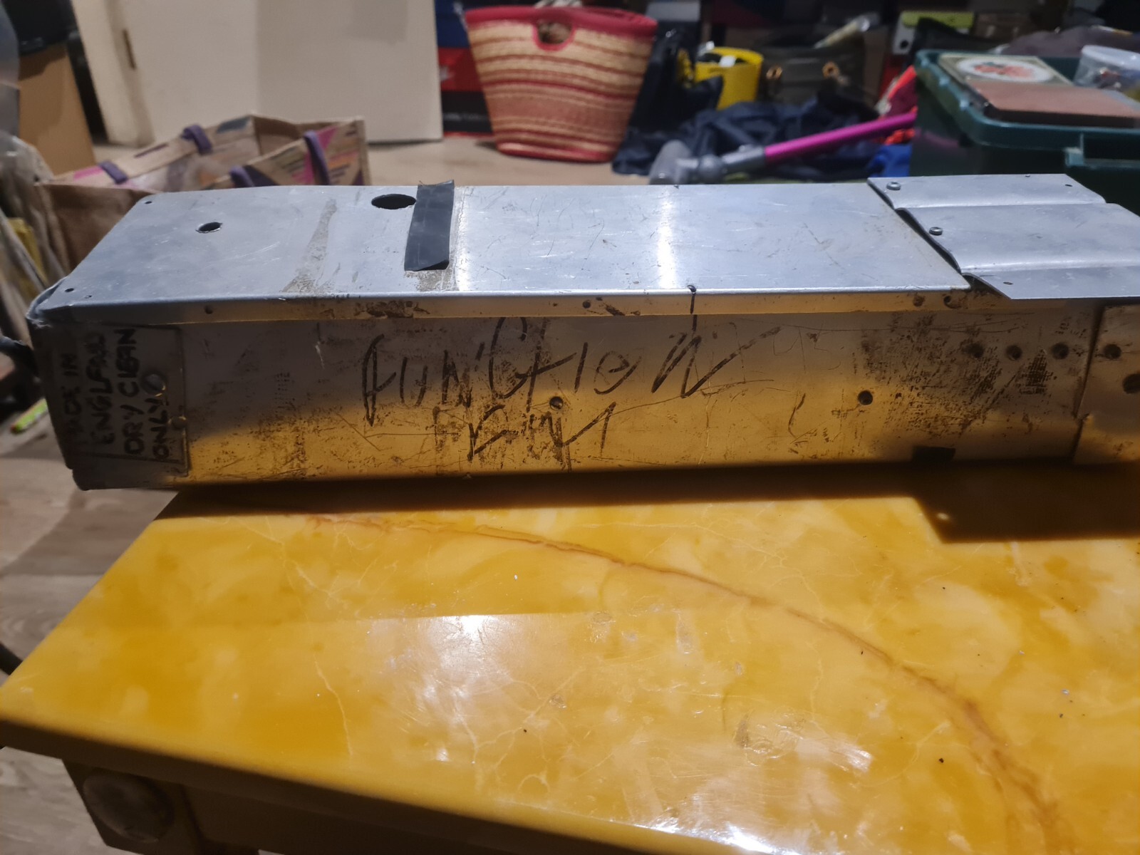
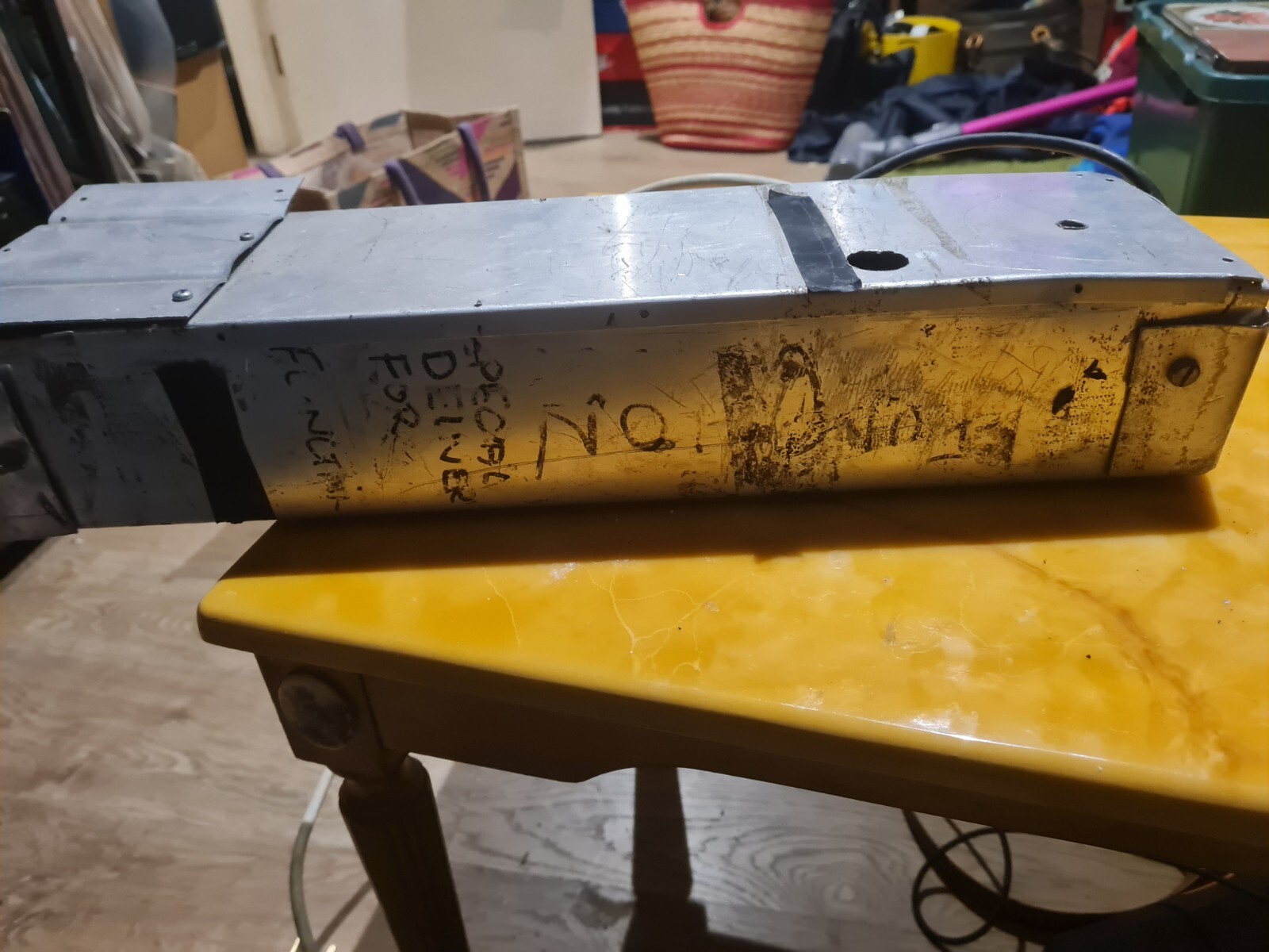
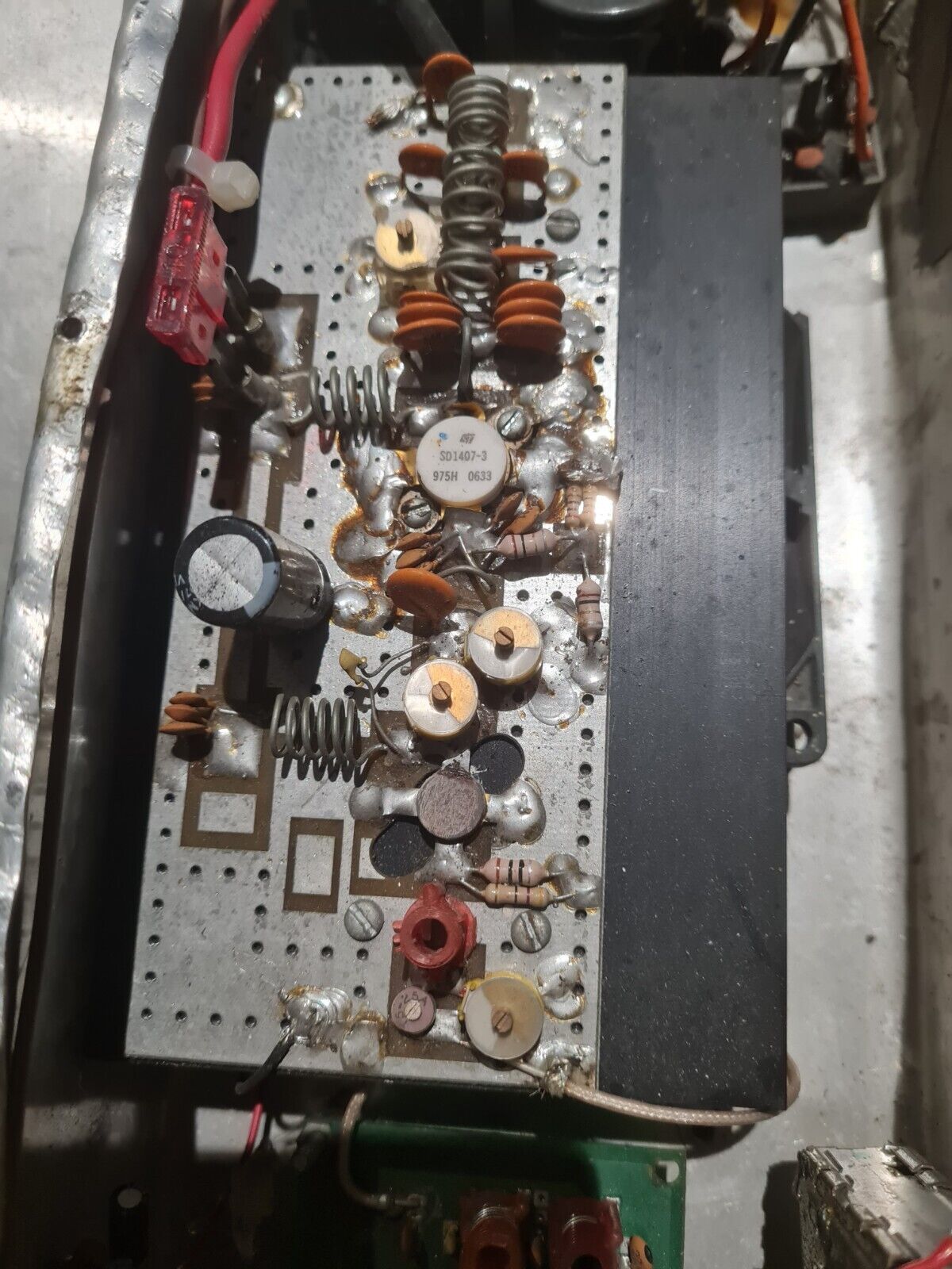
SD1407 can't be original device from 1994 and looks like 2006?
....I remember hearing a Function FM on 95.4 around that sort of time 93/94 but not sure if it's the same one.
https://www.ebay.co.uk/itm/186889790092
SD1407 can't be original device from 1994 and looks like 2006?
Last edited by teckniqs on Thu Feb 06, 2025 11:56 am, edited 2 times in total.
-
teckniqs
- proppa neck!
- Posts: 3365
- Joined: Thu Aug 21, 2014 11:37 am
Re: Old Rig
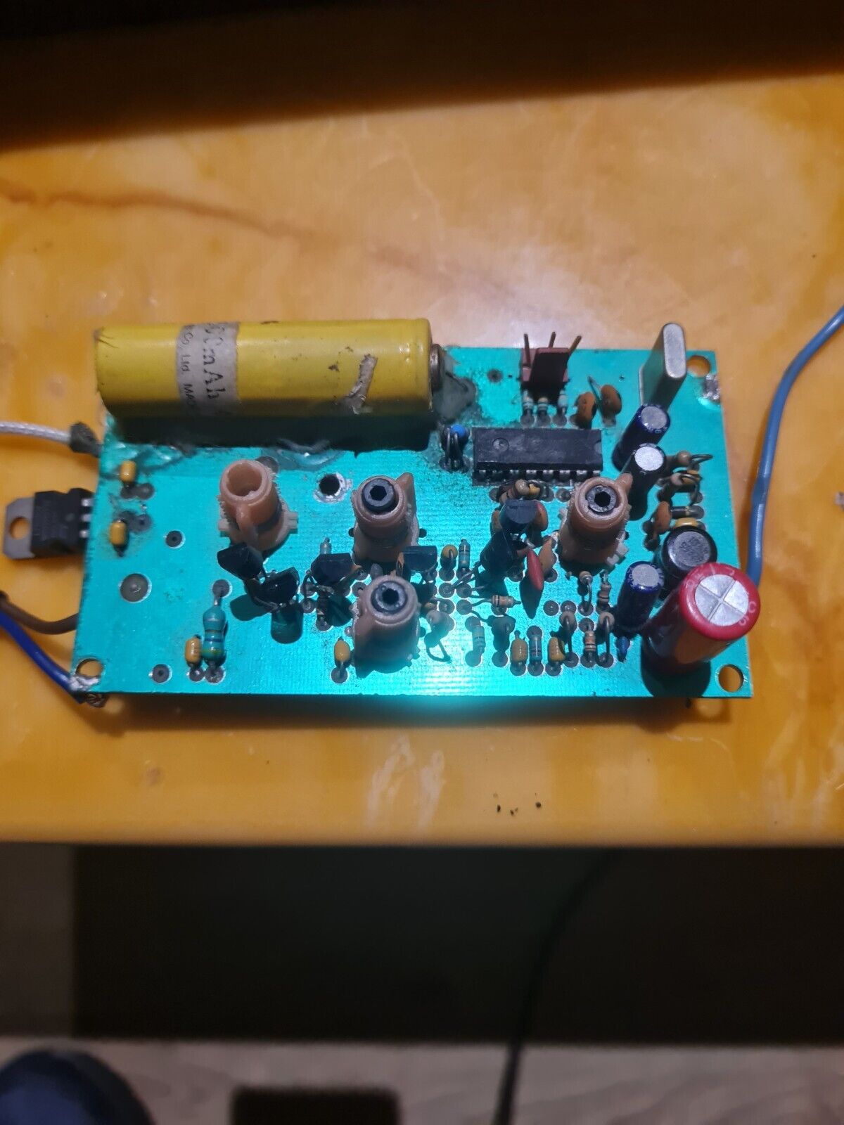
He's also selling the old May Ni-Cd Battery driver board from late 90s
https://www.ebay.co.uk/itm/186889953917
https://www.ebay.co.uk/itm/186889953917
-
shuffy
- tower block dreamin
- Posts: 425
- Joined: Sun Oct 05, 2014 3:55 pm
Re: Old Rig
Awesome find. Love the graffiti on the box. And looks like he's finished the folding with a pair of pliers
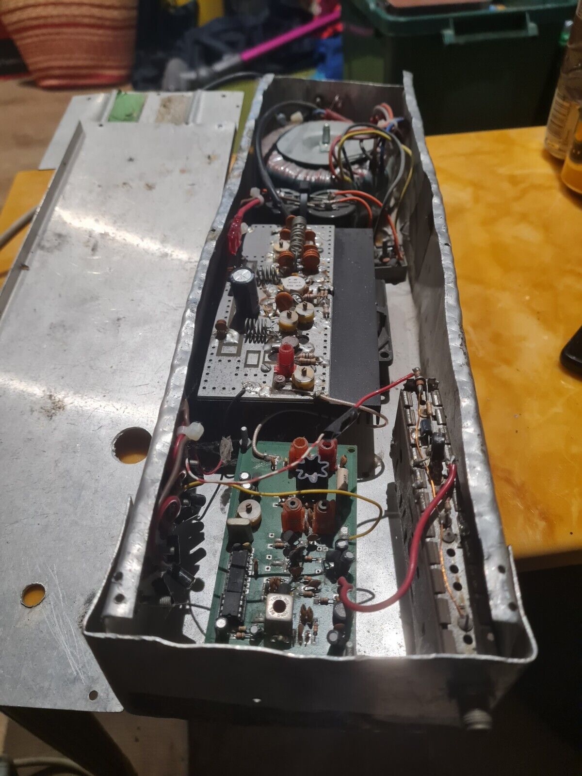
I'd say so, yeah. So probably had another owner later on.
Looks like there are 2 different PCBs on that listing if you look down the pictures. I'm guessing that on the driver board, that's just a PLL IC and I can't see a microcontroller. So was the PLL programmed once with a separate device to save a PIC - and the Ni-Cd keeps the PLL IC alive to preserve the config? Wonder if the 2nd PCB on the listing is the programmer?
He said shuffy! I said WOT? Woo!
-
jvok
- tower block dreamin
- Posts: 307
- Joined: Sun Aug 16, 2020 2:44 pm
-
1608cc
- big in da game.. trust

- Posts: 75
- Joined: Wed Jan 24, 2018 8:54 pm
- Location: Poland
Re: Old Rig
IDK why, but looking at photos of these old-style rigs are so satisfying  Even have a special folder with the most interesting '80 - early twenties designs I came across the web.
You do not have the required permissions to view the files attached to this post.
-
Albert H
- proppa neck!
- Posts: 2988
- Joined: Tue Apr 05, 2016 1:23 am
Re: Old Rig
The 0633 on the SD1407 isn't a date code - it's a batch number. I had a Shortwave Linear PA with a pair of 1407's that was built in 1989 or '90 and had the same batch code.
The '1407 was widely used from the early 90s. It had awful gain at Band II (7dB at best) but was reasonably unburstable! When Steve may was turning out junk like that, some of us were using proper VHF transistors including the early power FETs. The SD1407 had the advantage that it was dirt cheap - if you phoned around, you could find them for as little as £5 each. The driver transistor used to cost more!
I built a few rigs in that era with MRF150 output devices - 50V supply, 12 Watts drive, 150 Watts out - an early power FET. One PA design that we made a few of used a pair of 2N3375s driven by a pair of 2N3866s at 28V for the driver, followed by the MRF150 at 50V supply. The tuning was achieved by stretching or compressing some of the coils - trimmers that could handle power like that were getting really expensive by then. Our circuit was quite "broadband" for its day - the PA would work well over about a 3 MHz span without adjustment. A number of these went to Eastern Europe in the late 80s.
"Why is my rig humming?"
"Because it doesn't know the words!"
"Because it doesn't know the words!"
-
radium98
- proppa neck!
- Posts: 981
- Joined: Fri Aug 26, 2016 7:01 pm
Re: Old Rig
2nd and 5 are my picture . Picture 5 is for a Db italy intermadiate frequency of a 900Mhz link stl .
and 2nd picture is my first smart kit sk1031 vco fm transmitter with 5 stages wich drift , when i was a child 25 years ago . I am pretty sure that smart kit stole all the design from someone . even the 5 stage transmitter .
and 2nd picture is my first smart kit sk1031 vco fm transmitter with 5 stages wich drift , when i was a child 25 years ago . I am pretty sure that smart kit stole all the design from someone . even the 5 stage transmitter .
-
Albert H
- proppa neck!
- Posts: 2988
- Joined: Tue Apr 05, 2016 1:23 am
Re: Old Rig
The "Smart" Kits were not at all "smart"! A friend of mine had one of their "15 Watt" transmitters that drifted about 1.2 MHz in the first two minutes from switch-on, and carried on drifting as long as it was powered up! The oscillator didn't have any varicap, and was modulated by passing the audio into the base / emitter junction of the oscillator transistor. The capacitors in the oscillator were the cheapest ceramic jobs they could find!
I tried to stabilise it for him - I changed the capacitors in the oscillator for silvered mica types and NPO ceramics, and a more rigid oscillator coil, but it still drifted. I added a varicap, bias circuit and the relevant capacitors. It was better, but still drifted. I added a voltage regulator in the supply rail to the oscillator, which helped a bit. The drift was still unacceptable.
I connected a simple PLL circuit - on an "above-board" - over the oscillator. I took its input from the collector of the second transistor, and the output of the loop filter want to an additional varicap added to the oscilllator. The dividers were TTL, and the PLL board had its own 5V regulator. Stability at last! It stayed bang on frequency from shortly after switch-on to switch-off (it took about 5 seconds to lock).
I spectrum analysed the 13.5 Watts that was coming out of the other end of the board, and found that 2 Watts of it were harmonics! There was no proper output filter - just a simple L-match. Misadjustment of a couple of the trimmers could make it burst into random oscillation and spray even more mess all over Band II, the Air Band and up into the TV Bands! I added a proper filter, replaced some of the trimmers with fixed capacitors in parallel with smaller value trimmers, so there were no points at which it could "take off".
I mounted the whole thing on to a bigger heatsink, and constructed a case for it from thick PCB material. I added a supply fuse and an "idiot" diode so that incorrect connection of a battery (or "CB" supply wouldn't destroy it, and spray-painted its case with cobalt blue enamel paint.
The whole "upgrade" of the rig probably took longer than constructing a similarly powered rig from scratch, but I'd set myself the challenge of making it work properly, and was really pleased with the result.
It grew a second - identically laid-out - box that contained a split-band limiter and stereo coder. The whole kit - including the folded-down aerial and all cables - fitted into a small rucksack!
That little rig has been in use since the early 80s until today. My pal still uses it, powered from a "Leisure" Battery - into a folded dipole or a "halo" aerial - at music festivals all over Europe.
"Why is my rig humming?"
"Because it doesn't know the words!"
"Because it doesn't know the words!"
-
1608cc
- big in da game.. trust
- Posts: 75
- Joined: Wed Jan 24, 2018 8:54 pm
- Location: Poland
Re: Old Rig
Oh reallyradium98 wrote: ↑Sun Feb 09, 2025 6:45 am 2nd and 5 are my picture . Picture 5 is for a Db italy intermadiate frequency of a 900Mhz link stl .
and 2nd picture is my first smart kit sk1031 vco fm transmitter with 5 stages wich drift , when i was a child 25 years ago . I am pretty sure that smart kit stole all the design from someone . even the 5 stage transmitter .
I think 99% of kits are trash. Here is some old-style TX from the biggest polish electronic kit producer - CB transistors, push-pull and bulb as a power meter. Can't be done worse. It is a jammer not FM transmitter for sureAlbert H wrote: ↑Sun Feb 09, 2025 1:24 pm The "Smart" Kits were not at all "smart"! A friend of mine had one of their "15 Watt" transmitters that drifted about 1.2 MHz in the first two minutes from switch-on, and carried on drifting as long as it was powered up! The oscillator didn't have any varicap, and was modulated by passing the audio into the base / emitter junction of the oscillator transistor. The capacitors in the oscillator were the cheapest ceramic jobs they could find!
Of course there is still a remaining 1%. Proper VCO, matching circuits, preemphasis etc.
You do not have the required permissions to view the files attached to this post.
-
shuffy
- tower block dreamin
- Posts: 425
- Joined: Sun Oct 05, 2014 3:55 pm
-
1608cc
- big in da game.. trust
- Posts: 75
- Joined: Wed Jan 24, 2018 8:54 pm
- Location: Poland
Re: Old Rig
" The 'Pantek' ---The worst 3-watt FM transmitter ever built " Link - speaks for itself. Push-pull's were very common in '90 beacuse of lack of electronic components (especialy high grade RF ones) - at least here in Poland. They offer the best power vs cost / circuit complication level. Were hard to tune, unstable, put lot of harmonics into spectrum etc. But for young, newbie pirates the power level was the only criterium, so I think that;s the reaso why push-pulls were so popular then. You can come across a bunch of similiar circuits in that topology. Here's few examples form late 90s:
It is from times when OIRT standard (66 – 74 MHz) was still in use in ex-communist countires. Poor HF semiconductors such as BF259 or BD135 drove the whole pirate community.
You do not have the required permissions to view the files attached to this post.
-
Krakatoa
- no manz can test innit
- Posts: 111
- Joined: Tue Mar 07, 2017 8:57 pm
Re: Old Rig
-
EFR
- no manz can test innit
- Posts: 191
- Joined: Mon May 20, 2024 5:39 pm
Re: Old Rig
There was kit once, to build inside feedbox of regular FM yagi used to listen, power and audio was feed using same coax that did come down from roof. Supply voltage was used to set frequency, and if you lowered voltage, you had to lower audio input to avoid overmodulation....
Bird on yagi feed drops it from 90Mhz to about 70Mhz...
Bird on yagi feed drops it from 90Mhz to about 70Mhz...
You do not have the required permissions to view the files attached to this post.
Fight For Free Radio!
-
shuffy
- tower block dreamin
- Posts: 425
- Joined: Sun Oct 05, 2014 3:55 pm
Re: Old Rig
Yes! I actually think it was PANTEC with a 'C' and it was Italian. In 1984, Manchester (Stockport actually) had 2 stupendous FM pirates on air and I was inspired to have a go myself. I was aware of this 3W job from the small ads and spotted one in a local electronics shop. £15 sounded like a good deal, but I was barely a teenager and didn't know to leave well alone! I guess it was worth it for the education(?) but apart from burns from the red hot 2N3553s, the biggest impact the thing had was on my parents' telly.
There's more chat about it here, from back in the day. Usual suspects involved!
viewtopic.php?t=1268&start=20
He said shuffy! I said WOT? Woo!
-
FMEnjoyer

- proppa neck!
- Posts: 534
- Joined: Sun Oct 12, 2014 1:33 pm
- Contact:
Re: Old Rig
The Zenith electronics £15 ones make anything Chinese chip based seem like a dream rigs. They were a complete and total pile of doo doo. They hummed like hell, drifted all over, destroyed the entire band and most likely emitted 3 Watts of raw RF power across any frequency in VHF.
Every time I bought one I had this feeling I had done something wrong when putting it in the box, so I would be super careful to ground the PCB to the Aluminium box and wire it nicely, then I would switch on from a battery a nice stable source of power.... ERRRRRR TSH ERRRRR TSH ERRRRRR TSH ERRRR... same old doo doo again and again.
Must have been the worst RF devices ever to be built. Whoever designed that circuit knew it did not work and basically stole money from enthusiasts. ZENITH ELECTRONICS OWES ME £45 !! You could have sealed the disappointment of these rigs in a jar, open it this week and feel it even in 2025.
I used to creep past mine at the top of the staircase, and then curse when it changed frequency. Mine also sparked across the antenna terminal.. and I said I wonder what that spark is every 2 seconds ? Obviously static discharging from the dipole outside.
The odd thing was they were neat and tidy and had a nice fibreglass PCB and an idiot like me thought they were gonna be the next big thing on the dial.
I am surprised that DTI did not seize the lot of them being sold.
Funny to read about though.
"Dad can you write me a cheque please ? I'll give you the cash !"
I had one off someone in London £230 for 15W and also the NRG guy I think about 10-12W as advertised in Exchange and Mart or a mag a VFO and that was great, each stage all sectioned and shielded with baked bean can metal on brown phenolic pre-holed PCB with numbers on the side. Worked great.
And it must have been from one of those ads below, probably around 90-91 at a guess. I think I paid a bit more though like 130 rings a bell. Hard to recall now. He was very friendly chap and answered all my silly questions... "works with a dipole yeah ?"
viewtopic.php?t=3277
The dial is Glowing 88-108 , spin the wheel to light those Red LEDs , see signal needle rise.
-
FMEnjoyer
- proppa neck!
- Posts: 534
- Joined: Sun Oct 12, 2014 1:33 pm
- Contact:
Re: Old Rig
Or maybe LOOT, that green pink paper selling stuff.
The dial is Glowing 88-108 , spin the wheel to light those Red LEDs , see signal needle rise.