BH1415F with only VCO and PLL

Everything technical about radio can be discussed here, whether it's transmitting or receiving. Guides, charts, diagrams, etc. are all welcome.
Post Reply
OgreVorbis
big in da game.. trust
Posts: 95
Joined: Wed Mar 18, 2015 1:05 am

BH1415F with only VCO and PLL

Post by OgreVorbis » Fri Dec 23, 2016 9:44 am

I was wondering if the low quality of the BH chip is solely because of the MPX encoding or is there something bad about its PLL and VCO? It looks like these chips can be hacked to use an external MPX encoder/audio processing. I wonder how shitty they would be if you eliminate the MPX. Has anyone experimented with one of those cheap chinese CZH transmitters?

It looks like if you break the trace on pin 5 of the chip, you could solder an MPX signal there?

Image

Image

Albert H
proppa neck!
proppa neck!
Posts: 2777
Joined: Tue Apr 05, 2016 1:23 am

Re: BH1415F with only VCO and PLL

Post by Albert H » Fri Dec 23, 2016 11:22 am

Interesting idea!

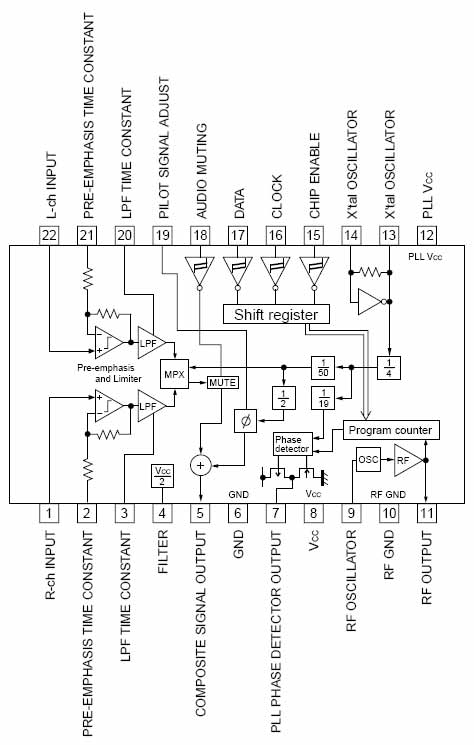
I just lifted pin 5 on a "car transmitter" that I have here. I injected a 1kHz tone to just try it out. Sadly, the spectrum - whilst improved a bit - is still horrible. The output still looks like a hedgehog on the analyser. I tried additional supply filtering to pins 8 and 12, which also helped a little bit, but to be honest, there's no real way to polish this turd!

I've also tried a couple of other PLL "transmitter" ICs, and the NS741 is nearly as horrible as the Rohm chips. There's one IC that almost makes the grade, but it's only available in SM packages and difficult to get hold of. It's an "SiS" part, and I've only ever tested one example in a "stereo test generator" made by Hameg (as I remember).

I'm afraid that's there's no viable short cut for a PLL exciter - you have to do it properly. If you're not sure about building RF gear (and it's NOT trivial), buy a good kit like the NRG boards available from New Zealand.

They're not cheap, but you do get what you pay for - a properly manufactured PCB, good quality parts, and a tried and trusted design. Stephen Moss designed the original so that it could be built by anyone with the ability to solder neatly and the ability to read instructions. The board is single-sided (with acres of groundplane) so that it is possible to remove and replace incorrectly installed or damaged parts. The components used are available anywhere in the world, and there is no pre-programmed PIC or other proprietary parts. Setting frequency is easy, and the spectral purity of the finished item exceeds the basic specifications for broadcast transmitters for RSLs (though you'd have to house it in a tamper-proof box and fit filter components for the modulation and supply connections).

I'll say it again - there's no short cut!
"Why is my rig humming?"
"Because it doesn't know the words!"
;)

Gigahertz
tower block dreamin
tower block dreamin
Posts: 258
Joined: Fri May 08, 2015 6:42 pm

Re: BH1415F with only VCO and PLL

Post by Gigahertz » Fri Dec 23, 2016 1:47 pm

A friend got hold of a second hand Ramsey FM30B 1watt version from the U.S

As we popped the lid I saw the BH1415F and thought "oh dear" but he put it on his analyzer and it didn't show any nasty sprogs. Seems to have half decent filtering !

Audio wasn't perfect but seemed to work ok can't expect too much from that chip. It was variable from 0 to just over a watt.

It's definitely not worth the $200 plus shipping and customs charge for 1 Watt that Ramsey are selling it for new!

But it's the most popular unit sold in the states for part 15 alongside the EDM transmitter... But commercial there isn't much else out there I suppose !
You do not have the required permissions to view the files attached to this post.

Albert H
proppa neck!
proppa neck!
Posts: 2777
Joined: Tue Apr 05, 2016 1:23 am

Re: BH1415F with only VCO and PLL

Post by Albert H » Sat Dec 24, 2016 2:40 am

The Ramsey effort is horrible on an analyser! There are lots of close-in spurs. There are also harmonics and the close-in rubbish guarantees that you'll annoy the neighbours! If the Ramsey is tuned to the low end of the band, there's a spurious product that appears in the air band only about 30dB down!

The EDM kit is actually well designed and care has been taken to keep it clean. It uses a discrete VCO and a separate PLL IC with a PIC to control it. The stereo coder uses outputs from the PIC for the pilot and the L-R subcarrier - intelligent use of the capacity of the PIC. The downside of the EDM job is that it's a kit and it's very expensive. >$200 for 100mW? Too expensive!

There's obviously a market in the 'States for products like these, but they'd have to be sold from within the USA as the rednecks are noted for their reluctance to buy anything "foreign"!
"Why is my rig humming?"
"Because it doesn't know the words!"
;)

OgreVorbis
big in da game.. trust
Posts: 95
Joined: Wed Mar 18, 2015 1:05 am

Re: BH1415F with only VCO and PLL

Post by OgreVorbis » Sun Dec 25, 2016 1:17 am

I found a BH transmitter and did the test myself too. You're right, it does improve a little, but it still has close-in sprogs on either side of the carrier. I don't know too much about RF design, but are these sprogs coming from a bad design inside the chip or could it be something like the loop filter (which is external I think)? I know it's probably not worth messing with this for a serious design, but I find it interesting if it's possible to get a good signal out of one of these.
The EDM kit is actually well designed and care has been taken to keep it clean. It uses a discrete VCO and a separate PLL IC with a PIC to control it. The stereo coder uses outputs from the PIC for the pilot and the L-R subcarrier - intelligent use of the capacity of the PIC. The downside of the EDM job is that it's a kit and it's very expensive. >$200 for 100mW? Too expensive!
Really, I had a look at their transmitter and it looks like it uses the BH1414 chip (not 1415, but still).

Image

Albert H
proppa neck!
proppa neck!
Posts: 2777
Joined: Tue Apr 05, 2016 1:23 am

Re: BH1415F with only VCO and PLL

Post by Albert H » Mon Dec 26, 2016 1:28 am

The one that I've examined used a separate VCO and a couple of stages of amplification. There wasn't any Rohm chip on the board. The stereo coding was done with a CMOS switch driven by 38kHz from the PIC.

There were a few obvious mistakes in the design, but nothing that would cripple it. Spectrum analysis showed that it was very clean. The LF audio response was poor because of the loop filter time constant - I wouldn't mind if it took 10 or even 20 seconds for the thing to stabilise and lock on frequency - it's a bad design decision.
"Why is my rig humming?"
"Because it doesn't know the words!"
;)

Post Reply